~# Instructions for Hak4Kidz DIY Cricket Badge 2024
Note: Make sure you read ALL of the instructions before turning on your soldering iron. This was you understand every step and will greatly reduce the chance of messing up the kit. We want you to have a cool badge, but we have a very limited amount of spare parts. If you are assembling this kit while not at a conference, you will have to order a spare parts kit from the Hak4Kidz Shop, or the individual part from another source.
Click the image thumbnails to see the full size. click the Back button to return to this page.
~## Check your parts
Verify that you have all of the parts listed in the BOM (Build Of Materials) below. If something is missing, either contact where you got the kit from or replace yourself. Links to the parts are included in the BOM.
BOM for Cicada Invada DC32 Badge 2024
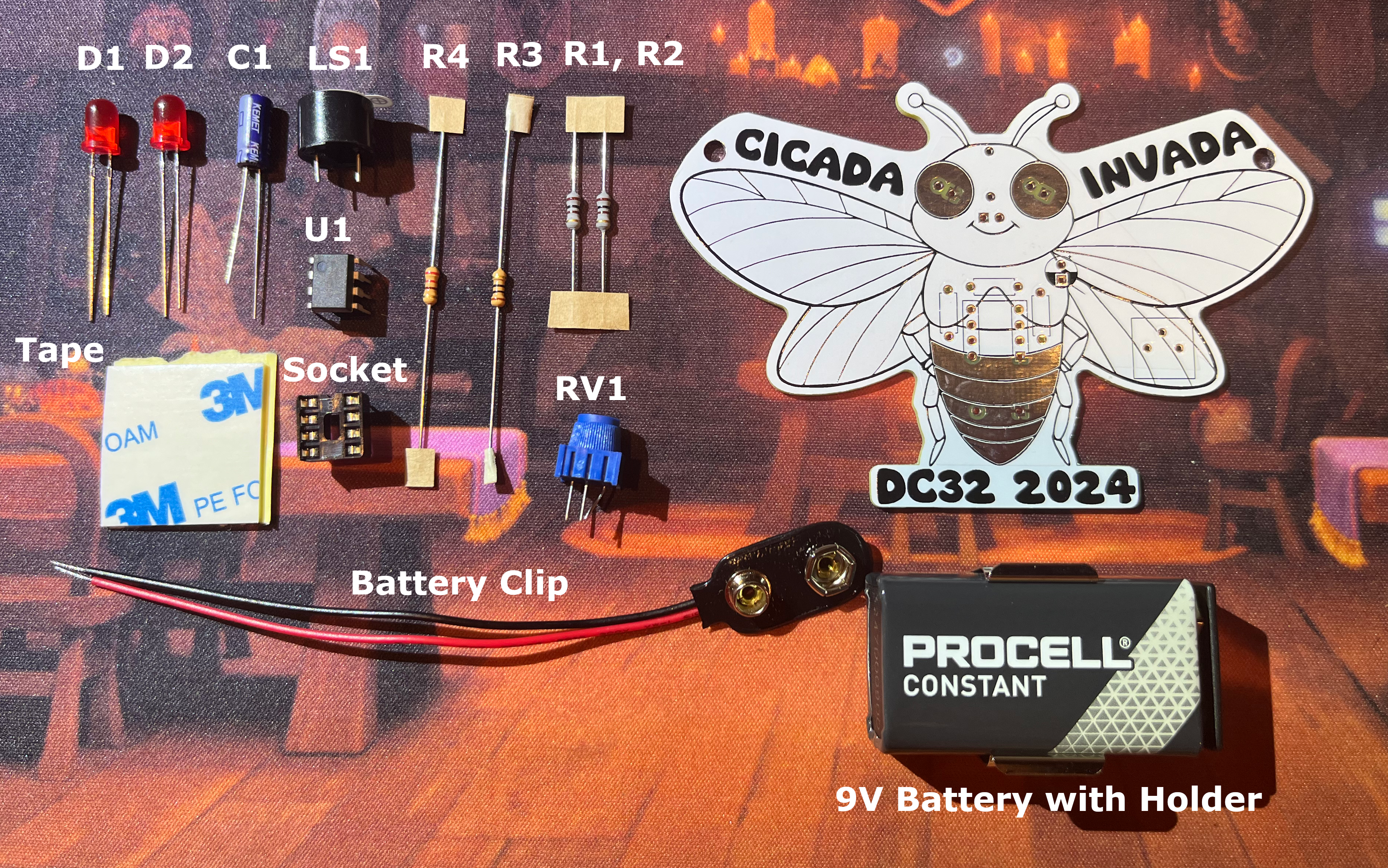
| Reference | Part | Value | |
|---|---|---|---|
| R1, R2 | Resistor: Axial | 100 ohm | |
| R3 | Resistor: Axial | 220 ohm | |
| R4 | Resistor: Axial | 10 ohm | |
| C1 | Electrolytic Capacitor | 100uf | |
| RV1 | Potentiometer | P203 3386P | |
| LS1 | Speaker | Piezo Buzzer | |
| BT1 | Battery holder: 9V snap clip | 9V Battery | |
| U1 | DIP-8 | ||
| IC DIP Socket 8 position | |||
| Battery Clip |
~## Getting ready
- Compare all of your parts to the picture above. Set aside the 4 resistors
- Have your solder spool nearby with a few inches of solder unwound from the spool
- If you need tweezers, have them handy
- Put other tools like your solder sucker off to the side until you need them
- Make sure your soldering iron is resting safely from flamable materials
- Turn on soldering iron and wait for it to heat up
- Now you are ready to begin
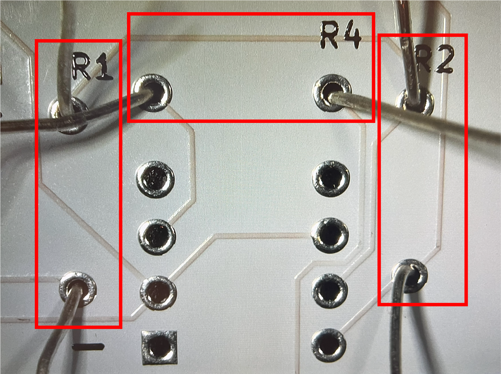
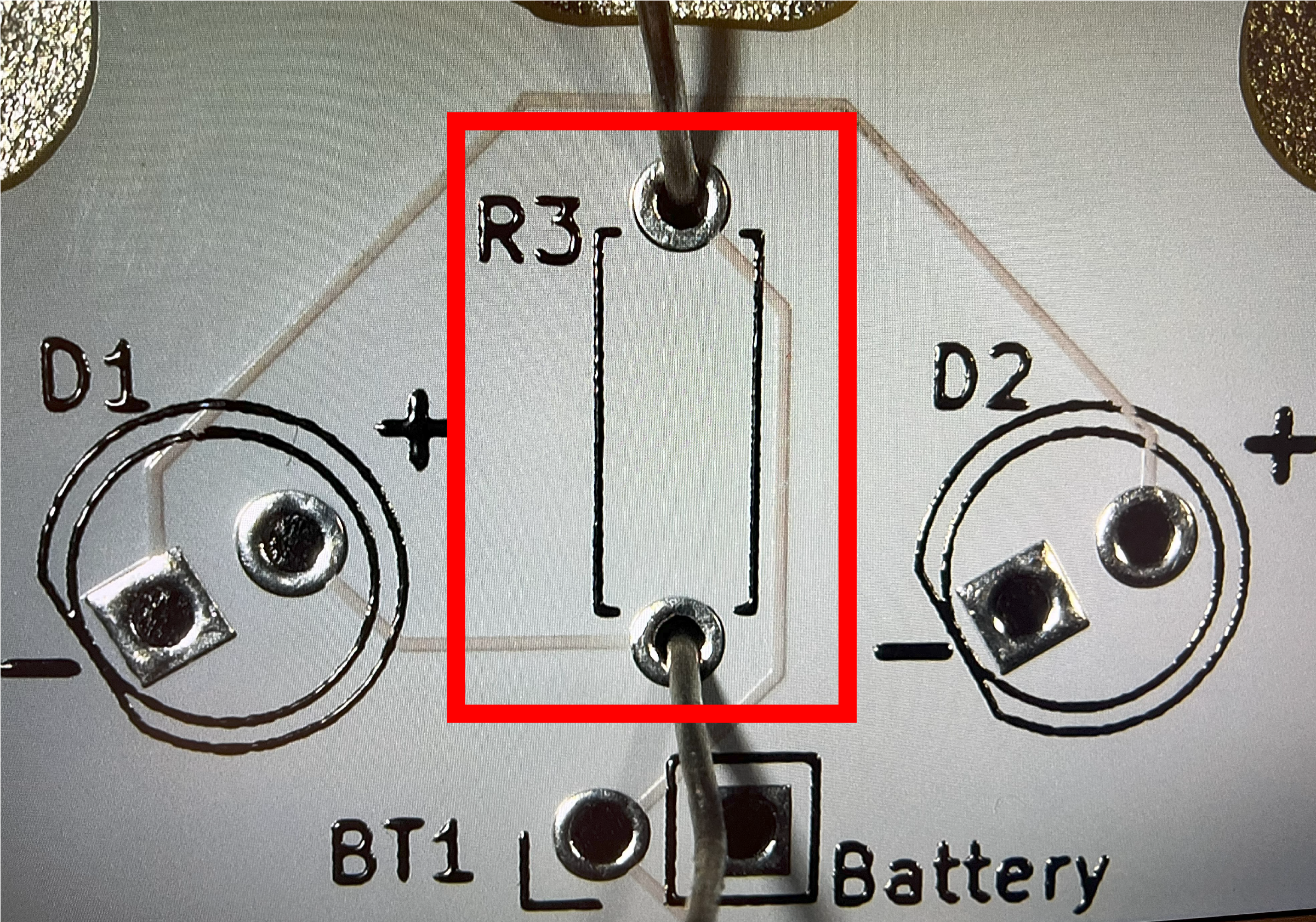
~## Building upwards - Resistors (R1, R2, R3, R4)
When sodlering, think about the parts and how they will increase the height of the board as you make progress. Starting with the flattest parts first will enable some of the parts to support the new parts being added, sometimes.
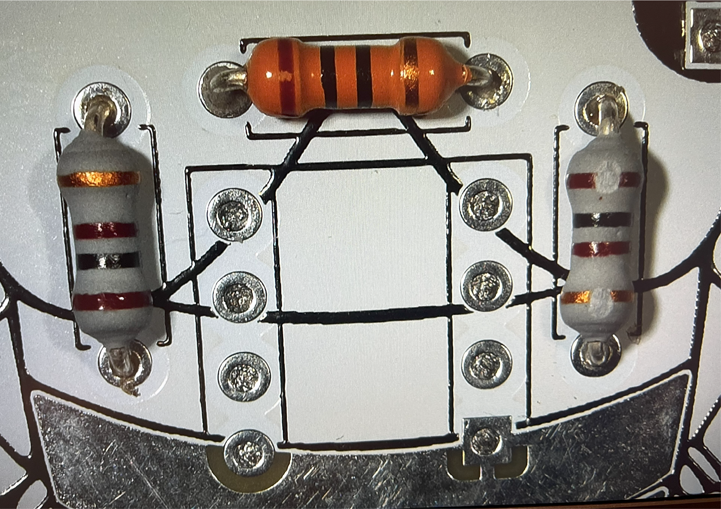
Resistors are typically a great place to start because they are the closest to the printed circuit board (PCB), and are not very tall. Make sure you are looking at the front of the board, which is the side the cicada is looking at you. Always check the pictures in each section before starting. You should know the before and after of each part before you place the soldering iron down.
- Insert the 4 resistors into the 2 holes on the PCB marked with reference numbers R1, R2, R3 and R4. Each resistor goes into it's own pair of holes.
- Starting with R1, put the 100 ohm resistor wires (also called leads) into both holes. You will have to bend the wires to make them fit into both sides. While holding the resistor down with a finger, flip the board over, and bend the wires apart to prevent the part from falling out as you add more resistors. After successfully soldering the leads, trim off the excess wires with a pair of wire cutters.
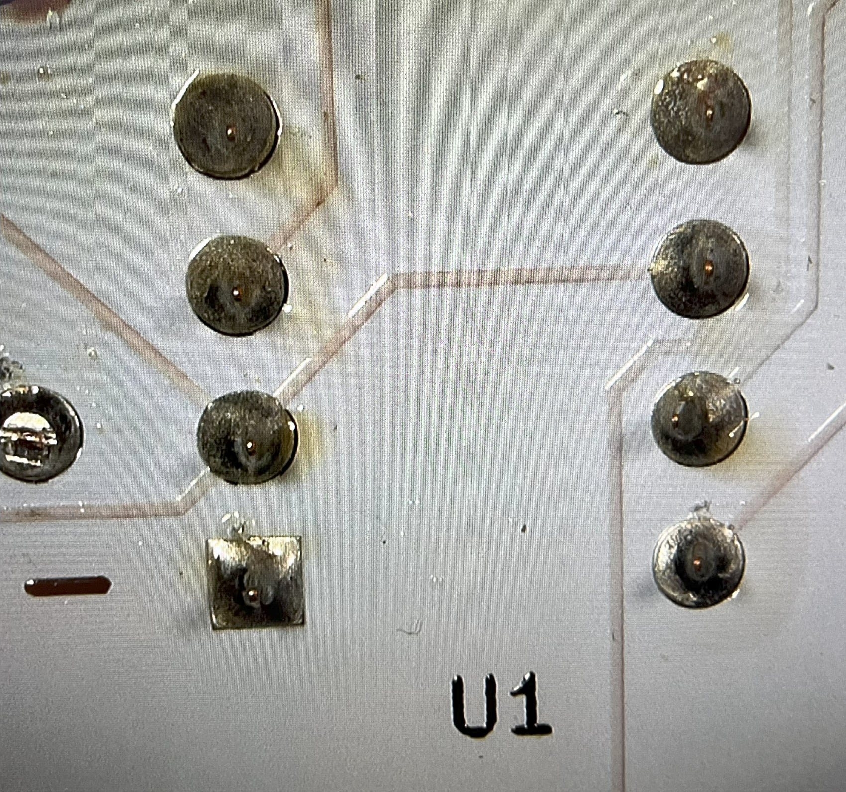
~## Dip-8 Socket (U1)
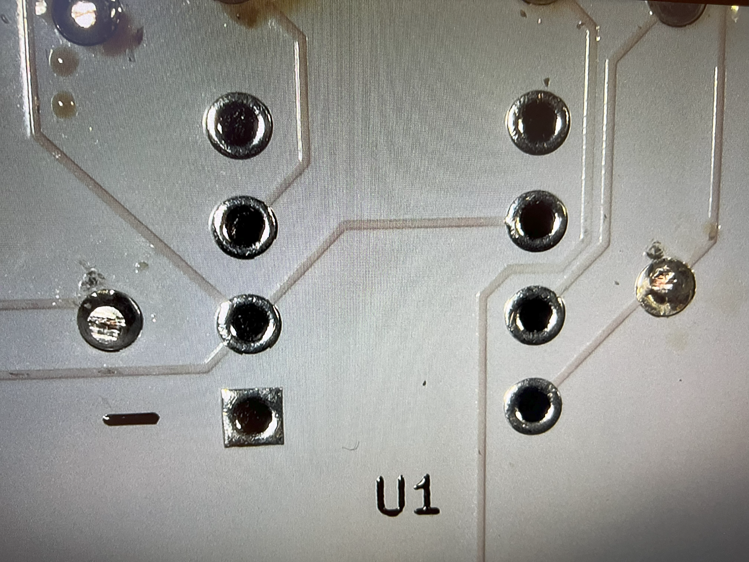
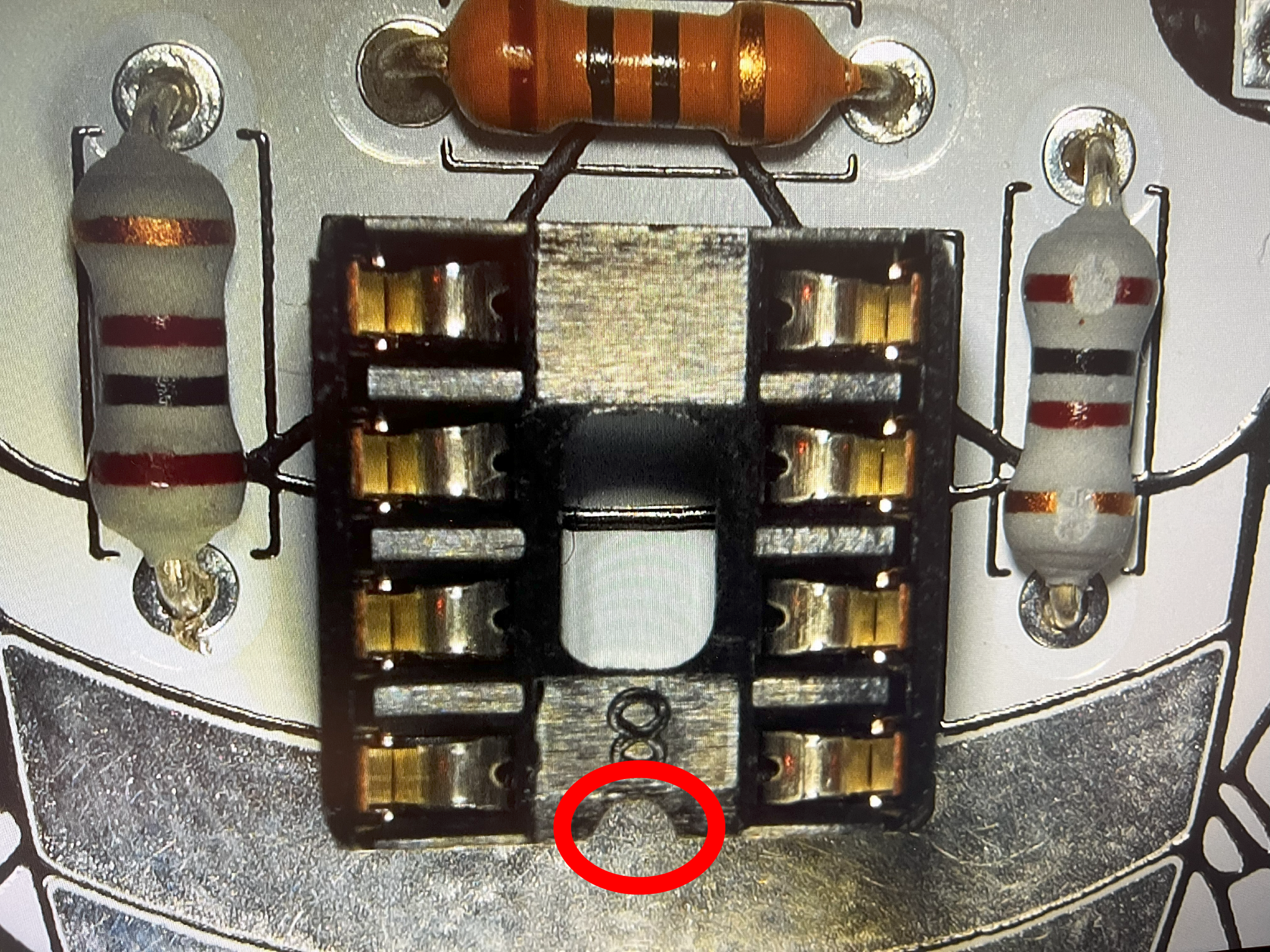
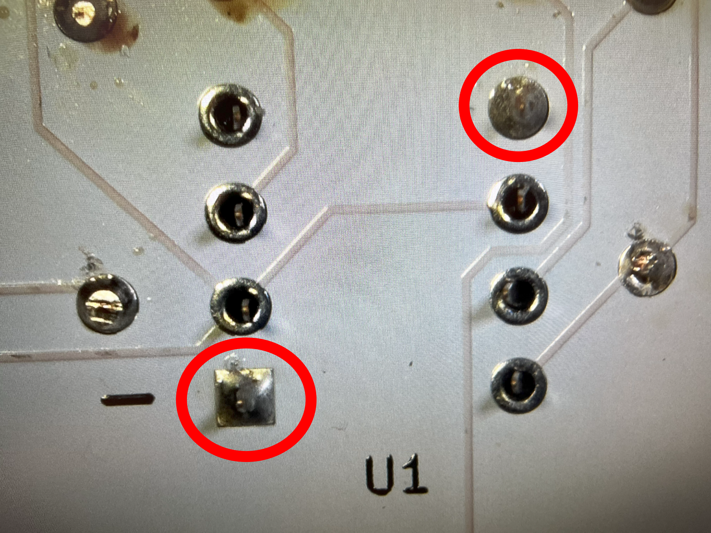
Locate the reference U1 for the 555 timer socket. Orient the socket so the tab faces downward towards the Cicada Invada's tail. You want to solder opposite corner pins first to make sure that the socket is securely placed into position. Once you know the socket is flush to the board, solder the remaining pins. IMPORTANT: Do not add the 555 timer IC chip until everything is soldered.
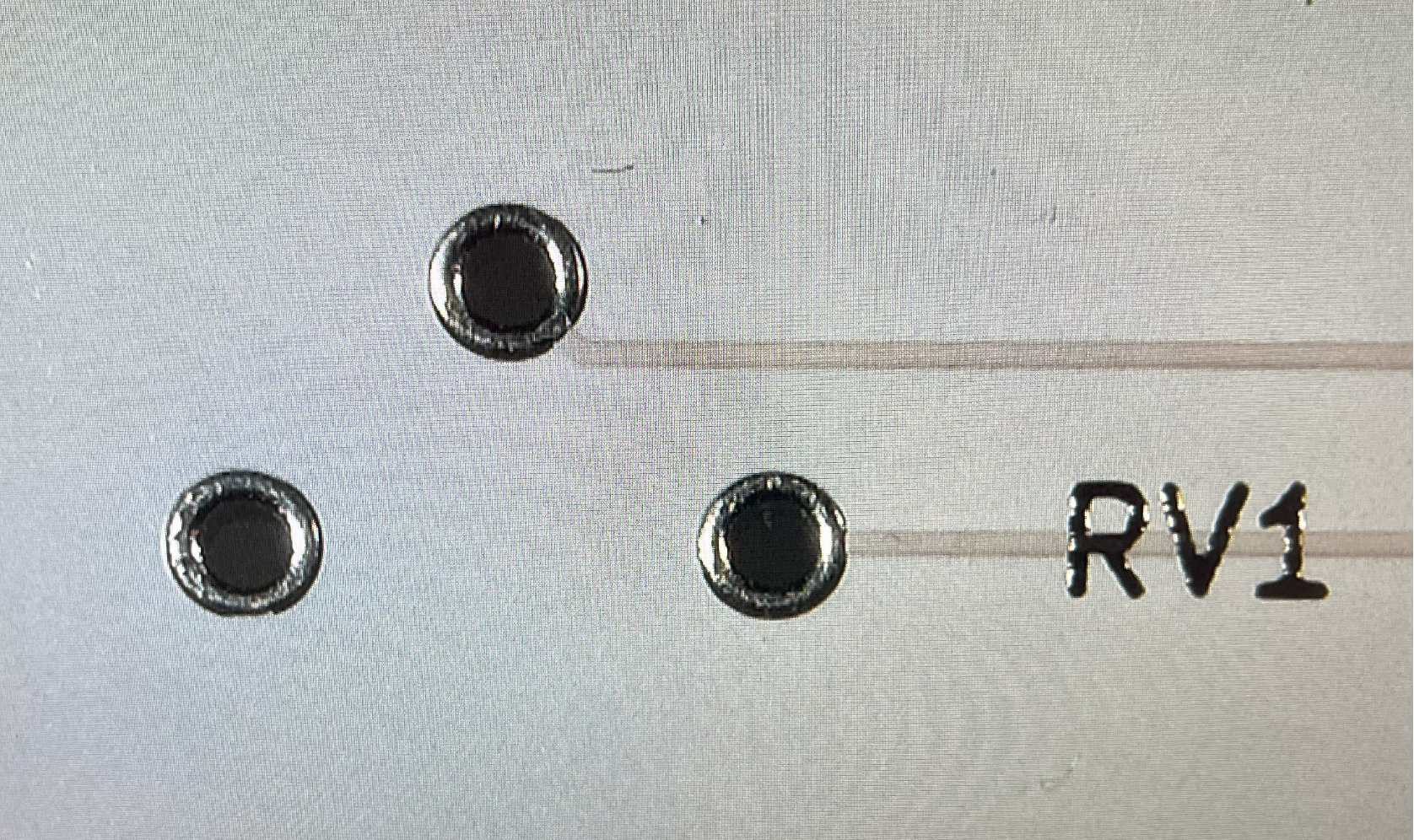
~## Add Potentiometer (RV)

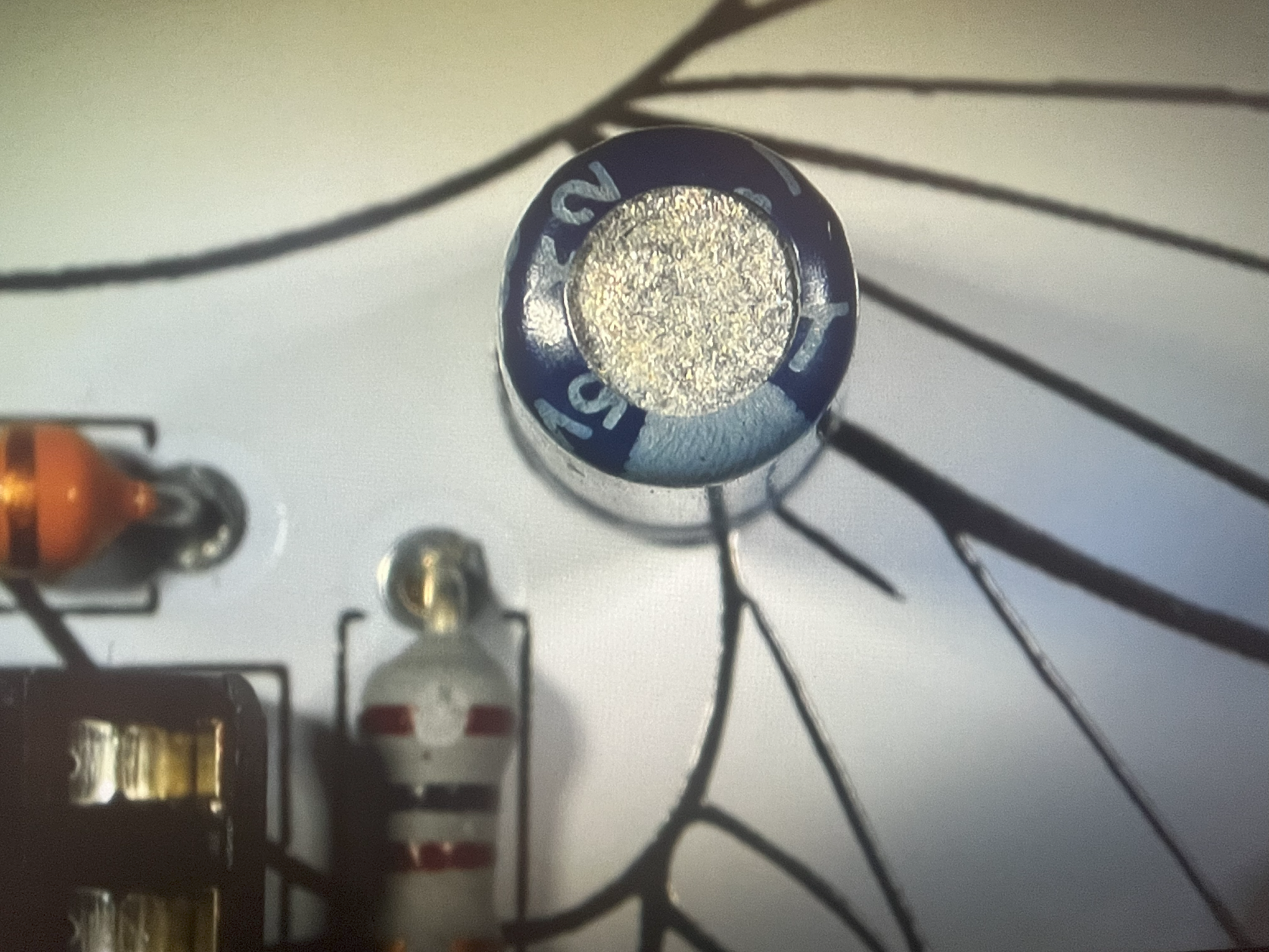
You can add the blue potentiometer (aka POTs or variable resistors). If your leads are bent, correct the bend carefull with your finger or a small tool. As you add it, you should notice the orientation is the fixed because they have 3 pins. After the pot is inserted into the board, bend the pins back away from each other. Don't solder yet. When you are done, your current progress should look like this picture. Solder when you are ready

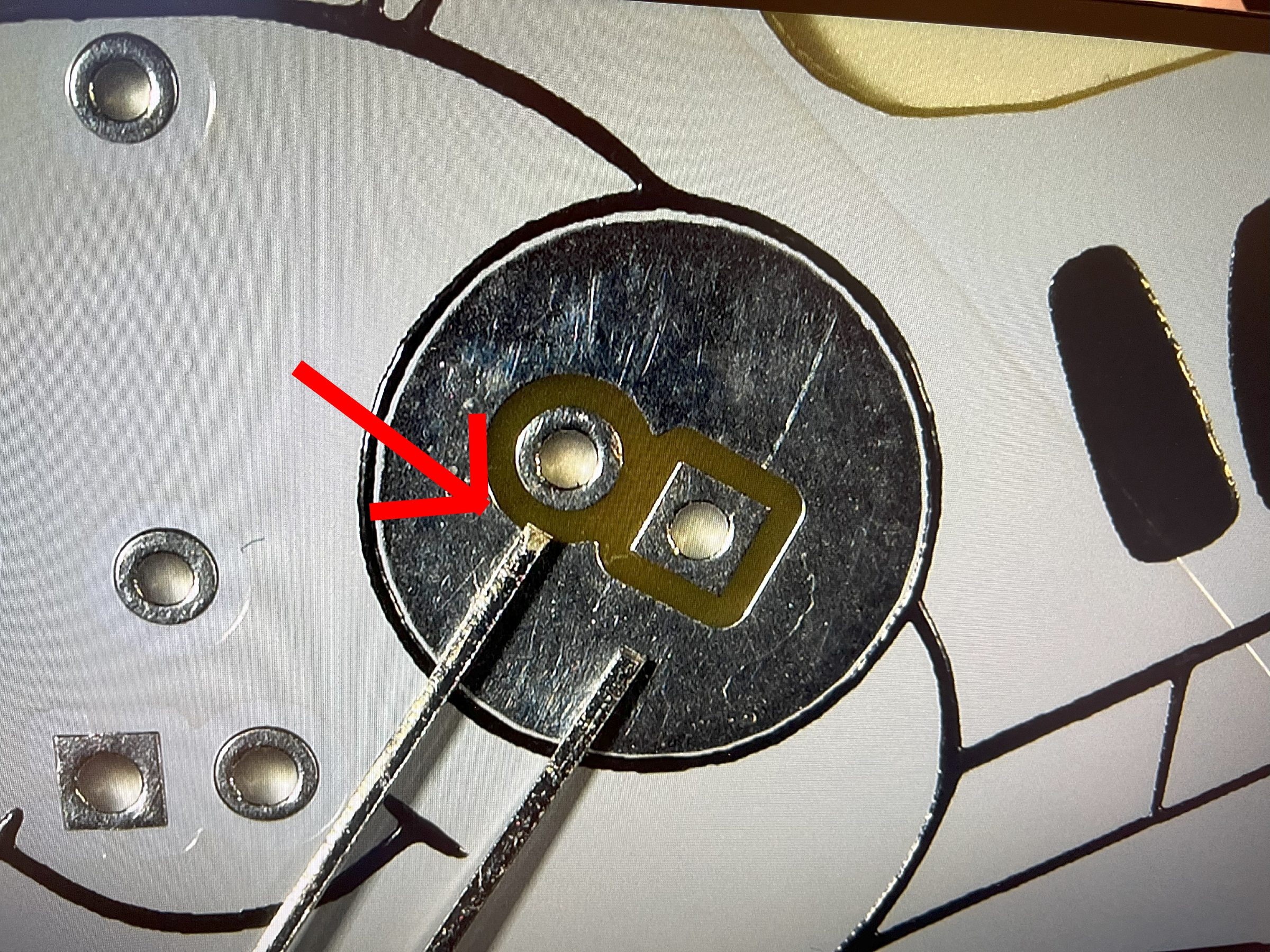
~## Potentiometer Completed (RV1)

In the blue triangle, you can see the flux is doing a great job keeping the solder on the pads and around the wires.
Trim off the excess wires with a pair of wire cutters.
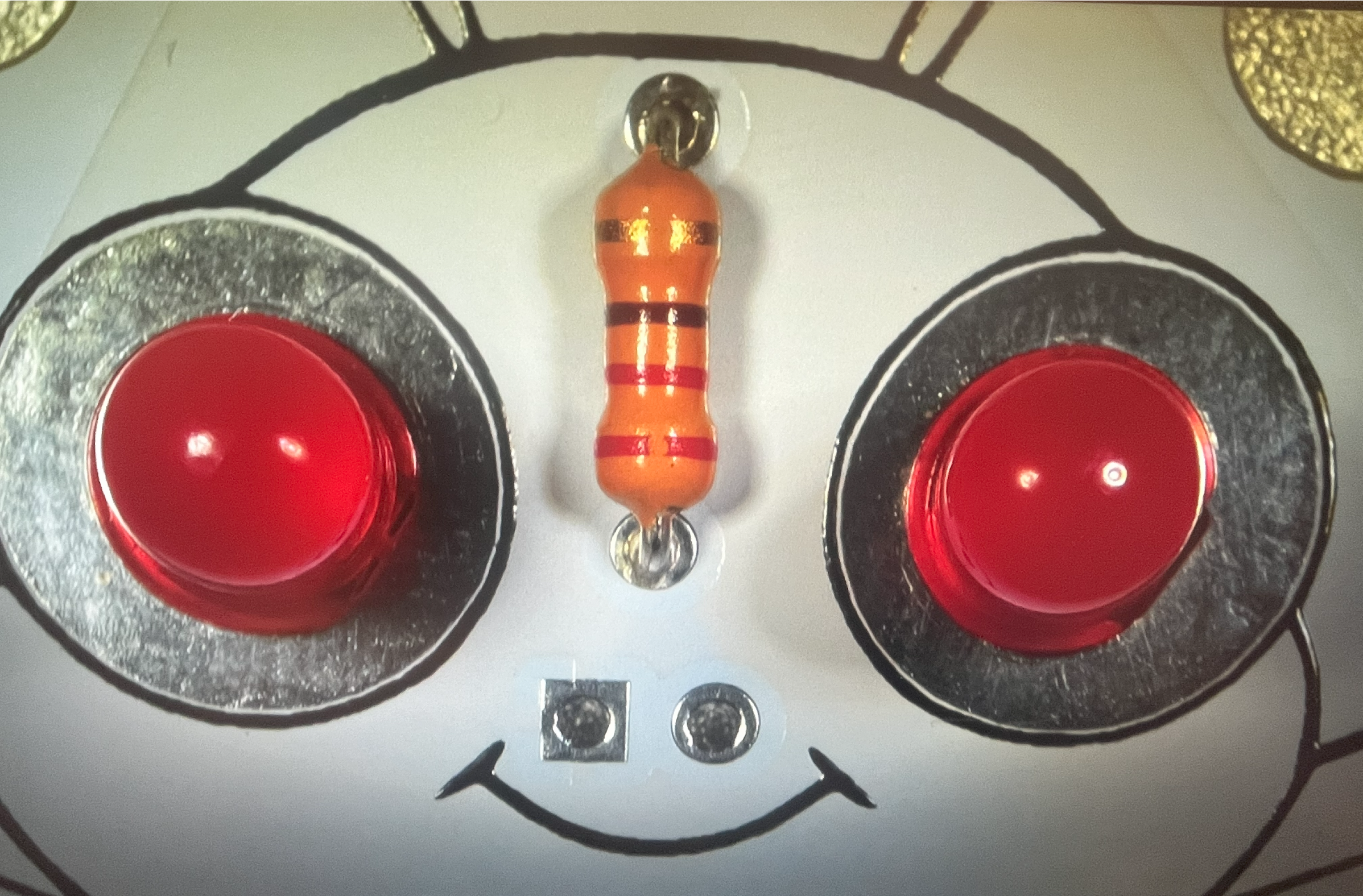
~## Red LEDs (D1, D2)
Carefully look at the end of each LED (Light Emitting Dioide) and you will see that the two pins vary in length. Make sure the longest pin is inserted as shown in this picture. This is super important because if it's not done correctly, then the Cicada Invada's eyes won't light up. You can start with either D1 or D2.
~## Bend Red LEDs (D1, D2)
You want to bend back the LED leads to keep them in place. I like to bend them back in opposite directions to avoid bumping, AND bend as close to a 90 degree angle. Doesn't need to be 90 degrees, just more than 60 degrees. These LEDs like to move out of place more than the other parts. Solder only one of the leads first, check the front of the board that the LED is flush to the board. If not, heat the solder while attempting to adjust the LED so it's flush. Then proceed to the remaining pins. Repeat for the other Red LED.
~## Red LEDs Completed (D1, D2)
After soldering the remaining pins, straighten out the leads. This makes it easier to trim off the excess wire with a pair of wire cutters. For these parts, I found using a little flux, if you have it, helps prevent the solder from bridging. Bridging is excess solder creating a short between two pins which messes up the project. If that happens, attempt to fix yourself or get help if it's too difficult.
Using flux may cause burns and dark spots on the beautiful board. That's easily cleaned with isopropyl alcohol and a cotton swab.
~## Red LEDs Trimmed (D1, D2)
This is how your board could look after trimming the excess leads. Those red bug eyes make my spine shiver.
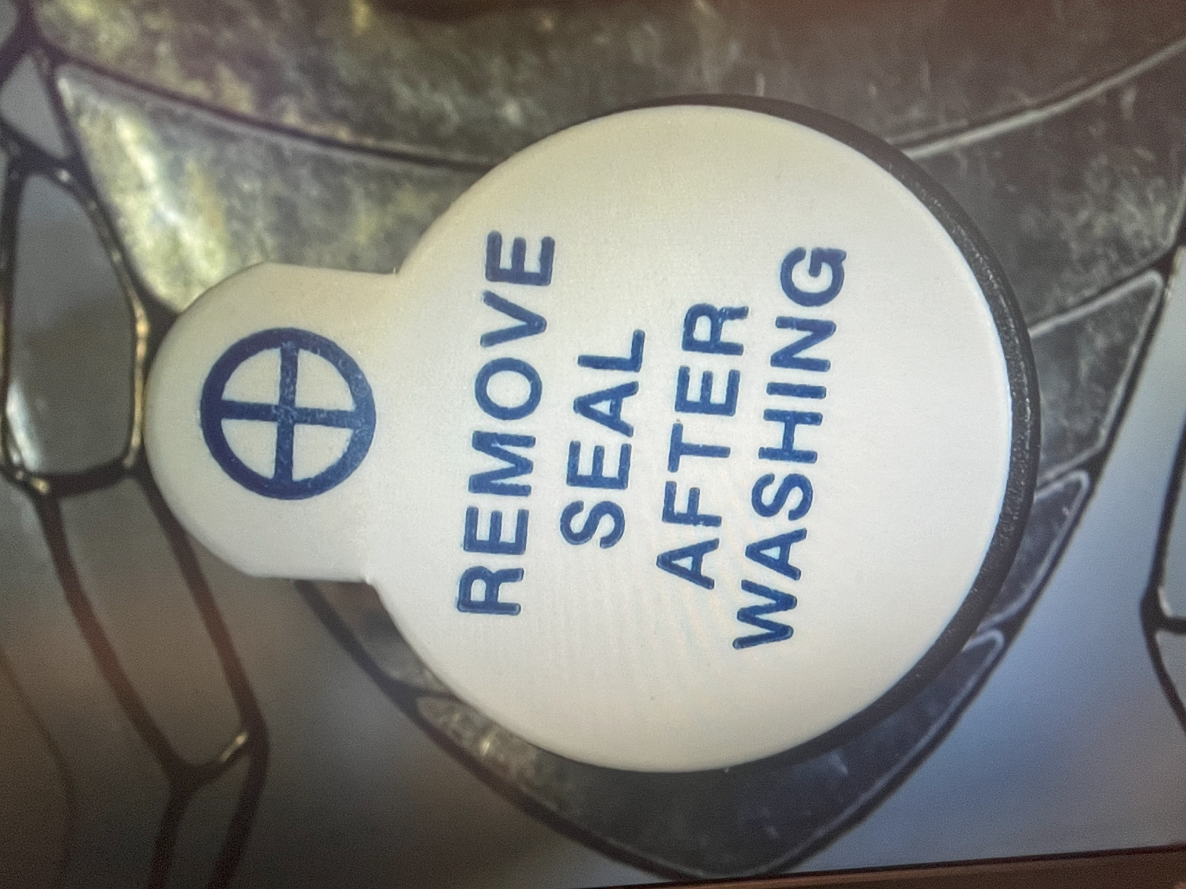
~## Mount Piezo Buzzer (LS1)
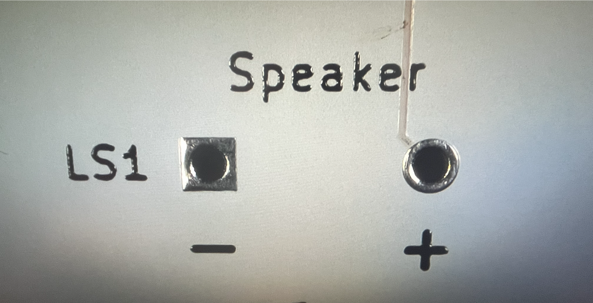
When adding the buzzer, for this project, the direction matters. Make sure you get good, clean solder joints and the buzzer is flush aginst the board.
~## Switch Completed (SW1)
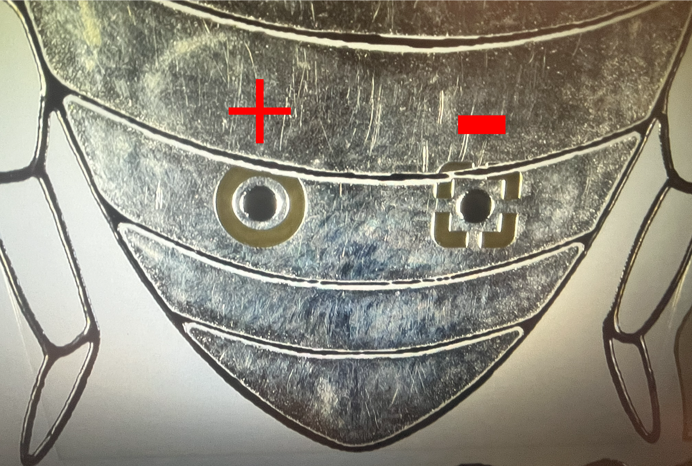
This is how your board should look after soldering the buzzer. Do you notice the '+' symbol? That means that's the side of the buzzer which is positive. Before certain, verify that the '+' on the sticker is in the same hole as the '+' on the back of the board.
~## Capacitor (C1)
Solder the capacitor (C1) on the top of the board. The capacitor has a stripe running down one side. That's the negative lead. Make sure the negative lead goes into the negative hole in the board.
~## Insert 555 timer (U1)
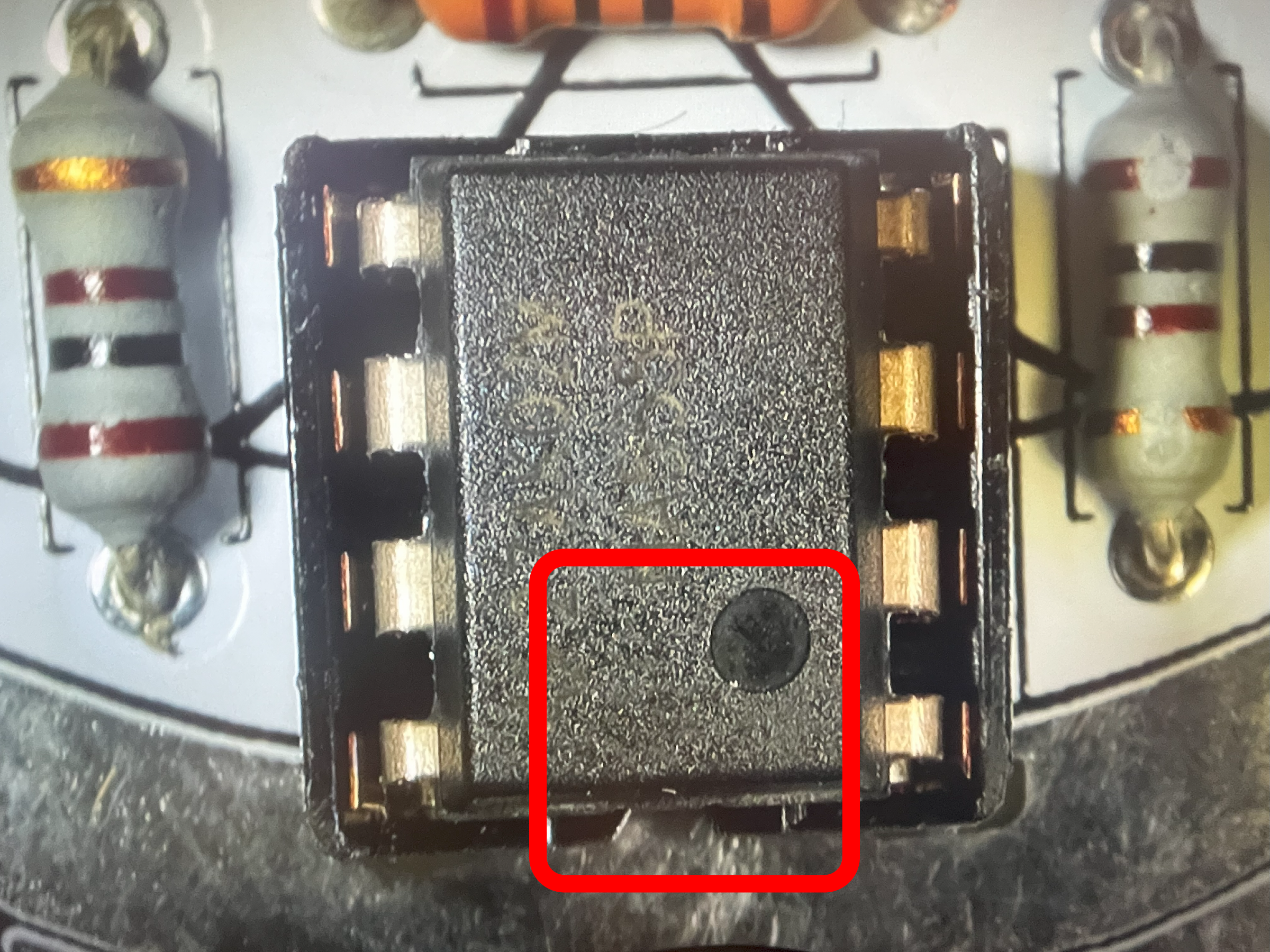
Now is a safe time to insert the 555 timer into the DIP-8 socket you soldered previously. Notice the 555 timer pin are wider than the socket? Slowly insert the 555 timer into one side, make sure the pins on the other side are correctly aligned and then gently but with some force, push the 555 timer into the socket. Check that no pins missed the socket holes. If so, remove the 555 timer, straighten the bent pins and try again.
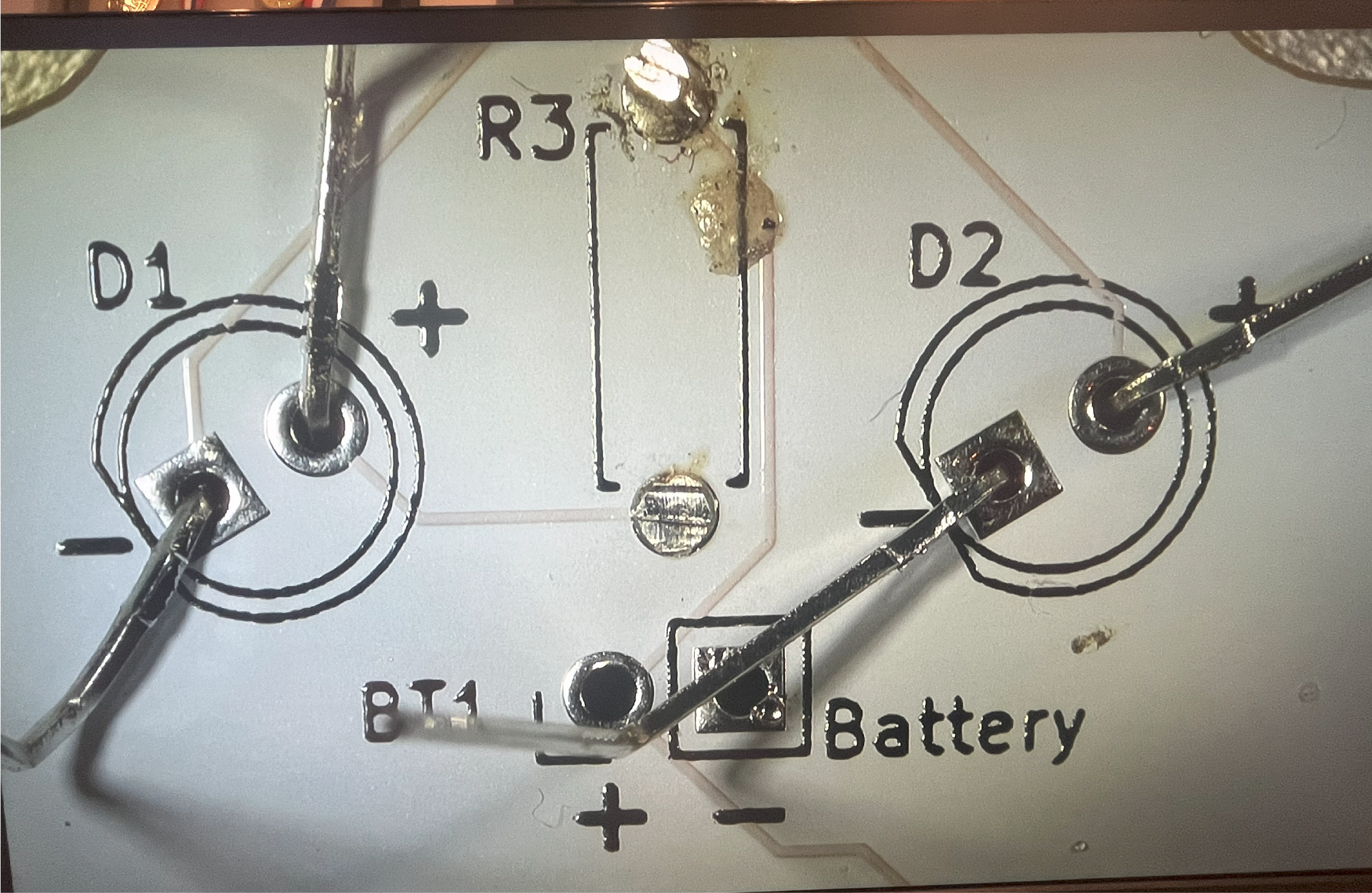
~## Battery holder location (BT1)
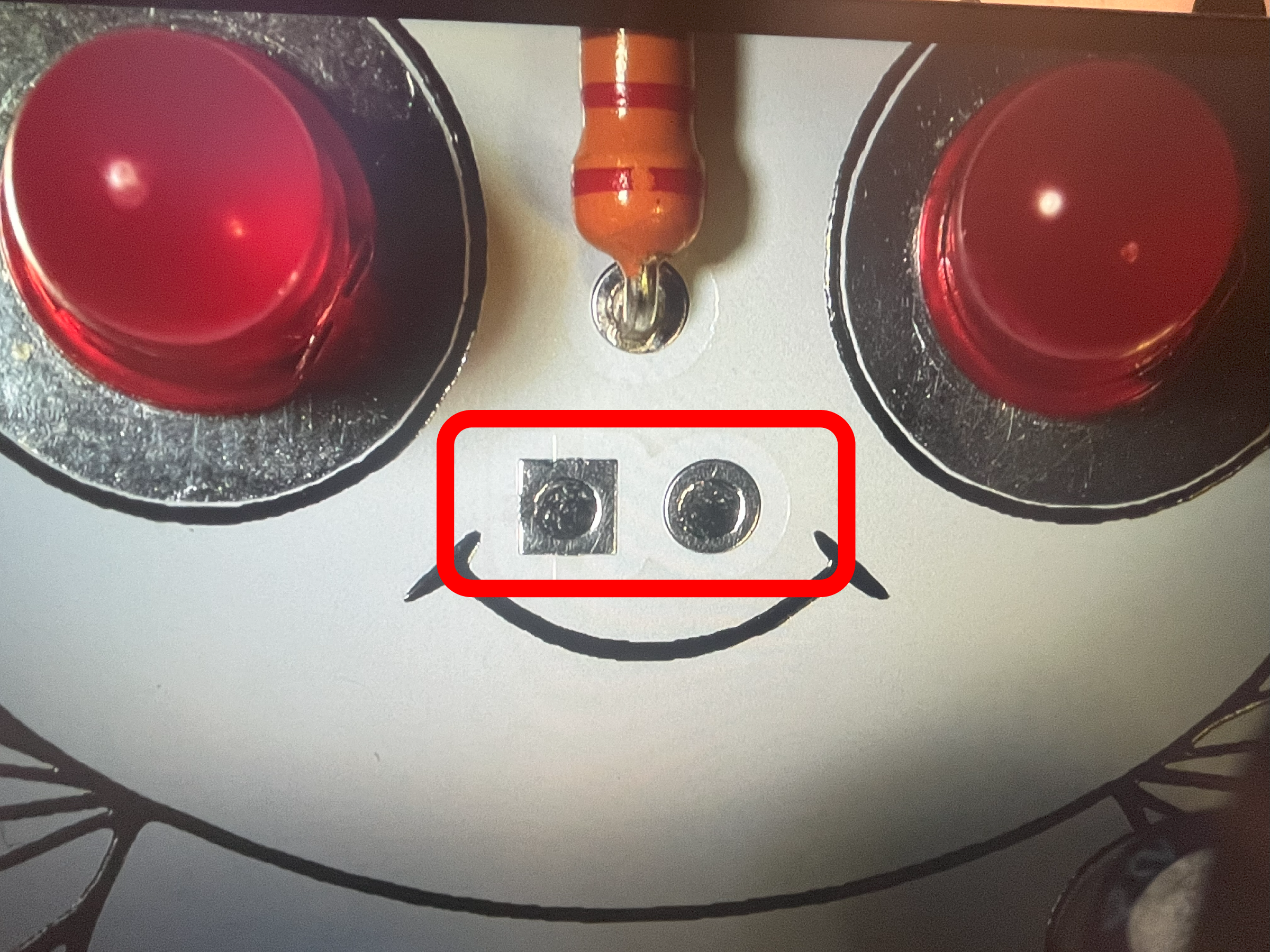
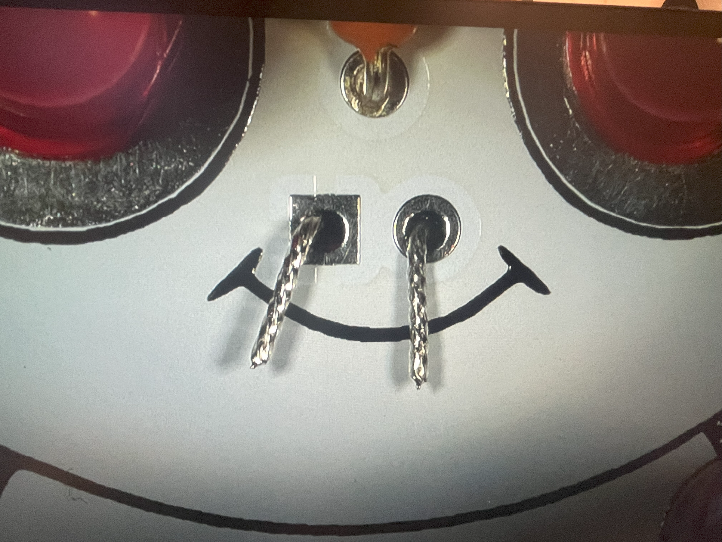
The battery 9V clip wires (leads) is the only part inserted from the back of the board and soldered on the face of the Cicada Invada. When done, it will look like 2 silver nostrils.
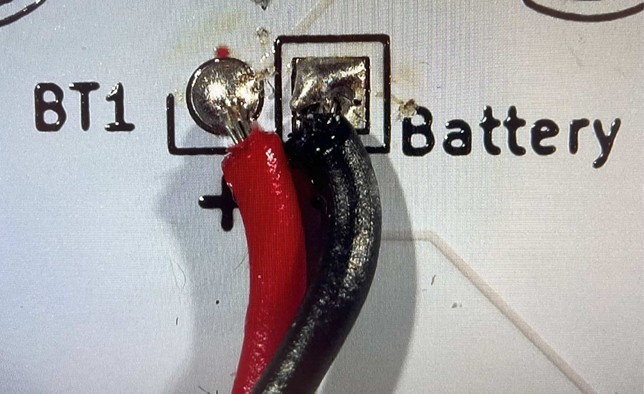
~## Battery Holder Placement (BT1)
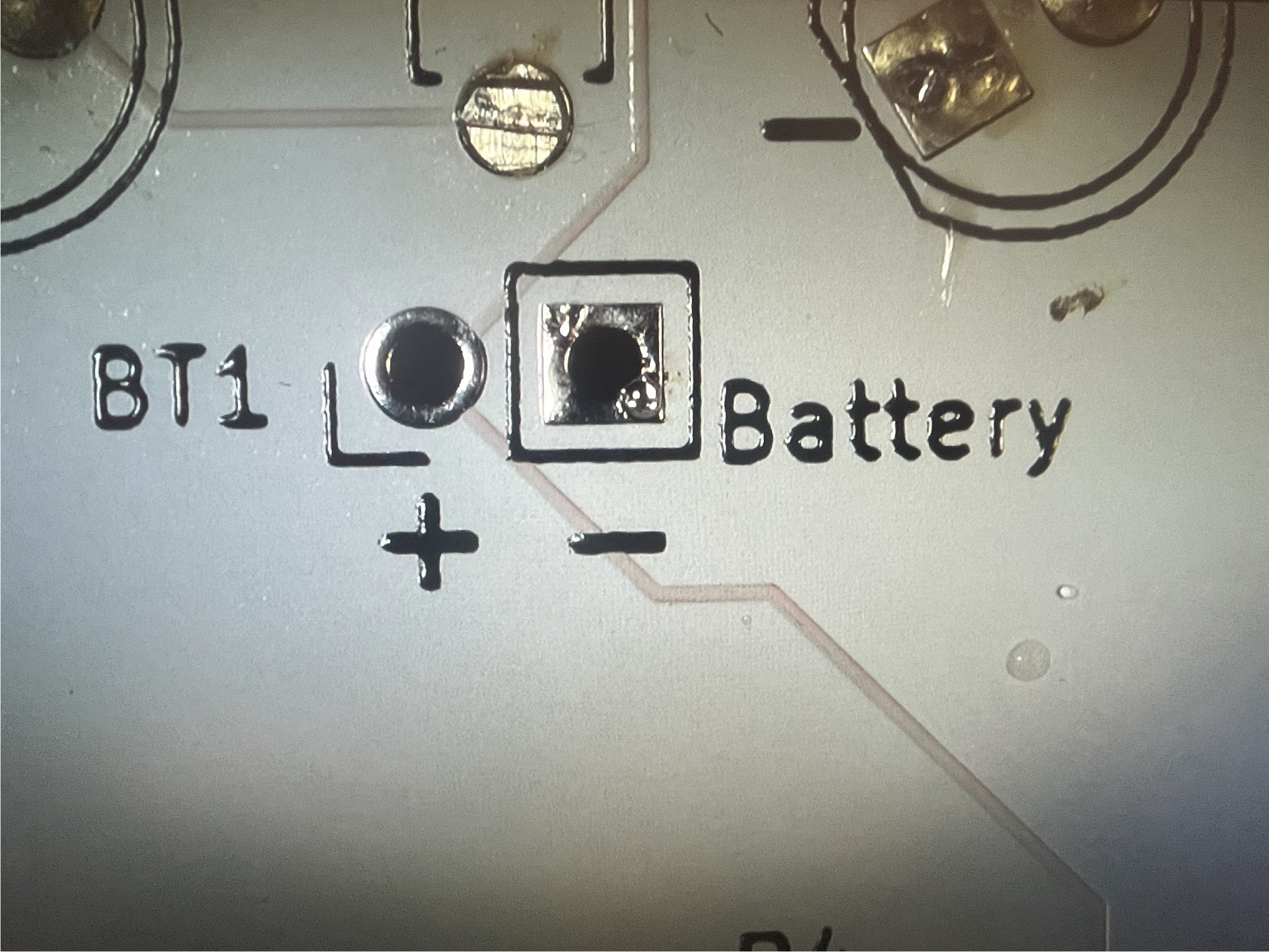
Insert the battery leads into the correct holes. Make sure the red wire is inserted into the '+' symbol.
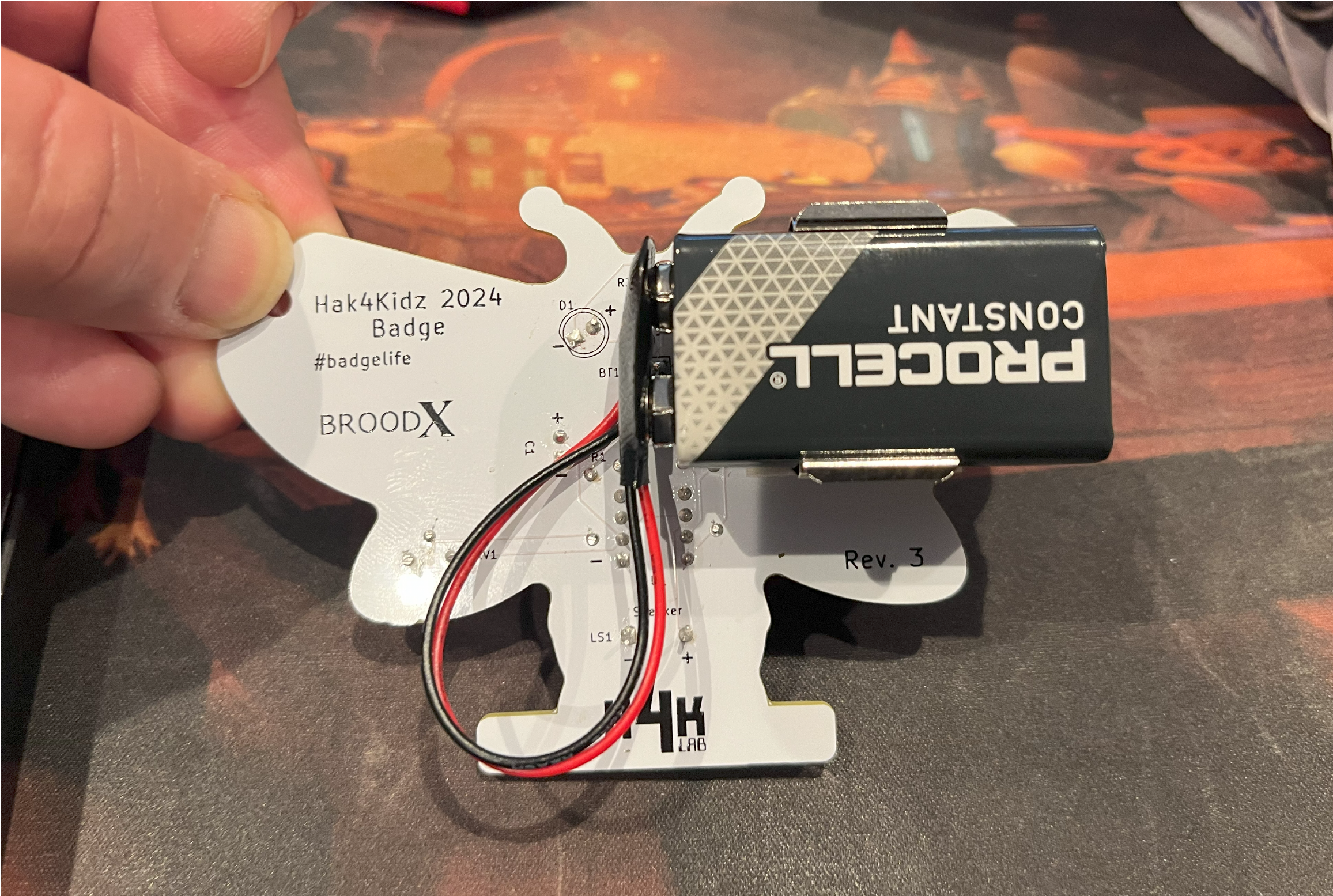
~## Battery Holder Mounting (BT1)
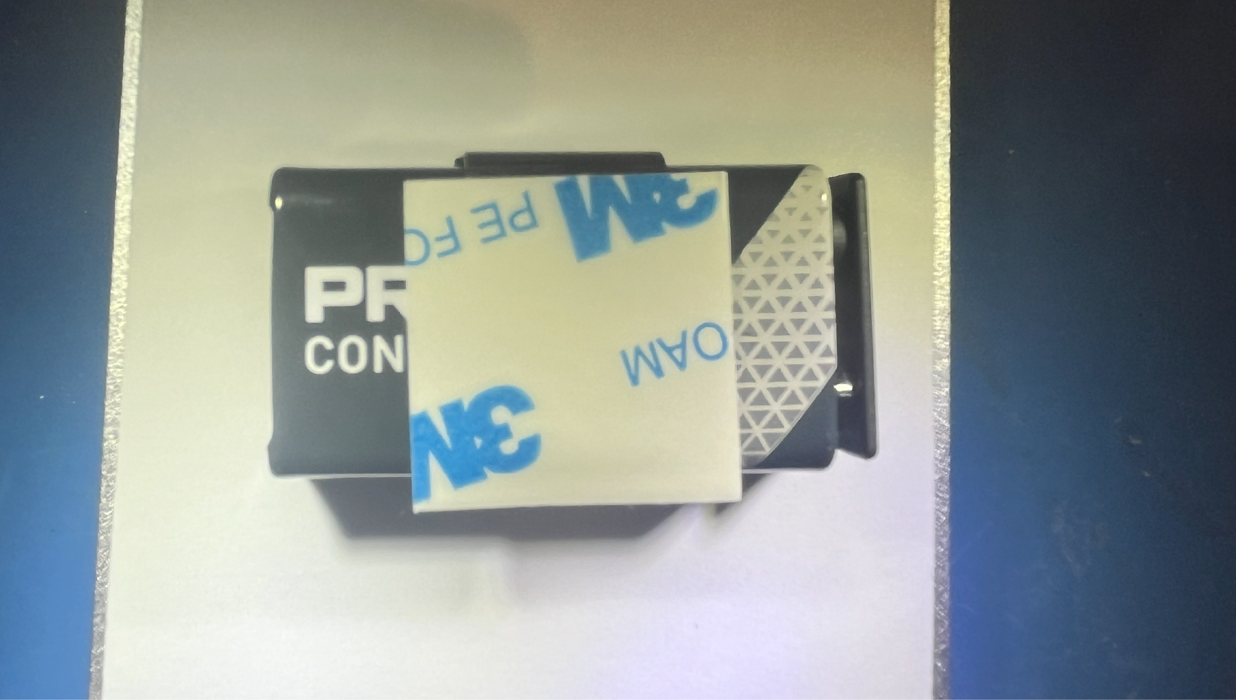
You need to attach the 3M square tape to the metal 9V battery clip, which is already clipped onto the 9V battery.
~## CHALLENGE: Can you make the Cicada Invada chirp so slowly that you can hide in a friend's home as a harmless prank?
We hope you enjoyed this soldering project. You can leave feedback with our Twitter account.